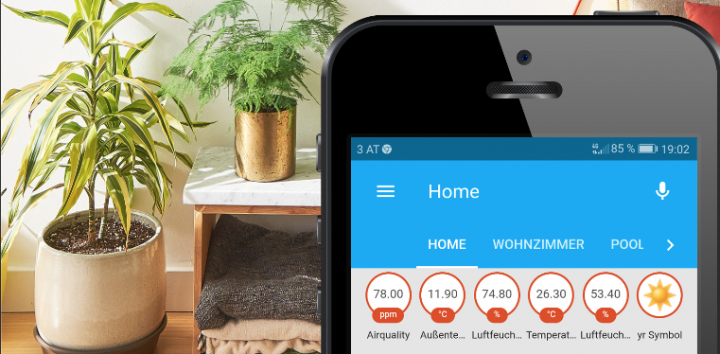
Telegram is a great way to receive home assistant (HASS) smart home automation information directly pushed to your Android or iPhone. By creating your own Telegram bot you get a lot of flexibility on sending home automation messages or even images from your security cameras to your mobile phone.
The first step of attaching a Telegram bot with your own home assistant (HASS) environment is to create your own Telegram bot. Contact the BotFather in Telegram as it is shown below and follow the creation wizard to receive your bot secret.
Then configure your Home assistant system to communicate with your newly created bot, as it is shown below:
# Example configuration.yaml entry for the Telegram Bot
telegram_bot:
– platform: polling
api_key: !secret telegram
allowed_chat_ids:
– 123456789
– 123456780
As a result you can extend all your Home assistant automation scripts to use your own Telegram bot to send out important notifications and images to your phone, as it is shown below:
Read more about Telegram integration and how to automate your home with the open source Home assistant platform within my own ebook available at Amazon.
As a dedicated Home Assistantuser for years now, I came to write an ebook covering all the important topics around home automation and tinkering your own Esp32 based sensors and actuators. Home Assistant is Open Source, written in Python and a lively community maintains over 3000 custom made components that allow you to control nearly everything in your home. For everything else there is the cheap and handy Esp32 or ESP8266 microcontroller that comes with builtin wireless network support and the capability to control any hardware you can think of. Soldering your own ESP8266 based sensors is really fun and allows you to add a lot of flexibility to your home automation. With a very low price tag of 5$ the ESP8266 microcontroller is a practical basis for all your custom made sensors and actuators. Read more about the details on how to solder your own sensors and how to attach them to your own home assistant system in my brand new eBook: ‘Open Source Home Automation‘.
Over the last months, I became more and more addicted to Home Assistant (Hass.io) and MQTT low cost wireless sensors. I was already familiar with several home and industrial automation systems that all come with a certain hardware (and price) and build upon a completely proprietary software stack. So long story short, I was searching for a good community-backed open source home automation system that is easy to set up and runs on my old Raspberry.
As home automation seems to be a broad area of interest I thought there should be hundreds of open source community projects out there. I was not as easy as I thought and there are not so many home automation projects out there. It seems as if the market is broadly dominated by large vendors that offer integrated solutions.
After some cumbersome fails I was finally able to find a real gem in the home automation area, which is called the Home Assistant, or short Hass.io. Home Assistant comes as a lightweight installation that perfectly fulfills following requirements:
Its lightweight, low resource consuming
Easy to set up
Nice web interface, that also comes pretty well with my tablet and smartphone (no app required, responsive web UI is great on your mobile device too) See a live demo here.
Supports automation scripts, such as turn light on at sunset
Best of all its written in Python and its open source
The first step towards building my own MQTT wireless weather station was to set up a Home Assistant instance on my old Linux laptop. If you already got Python3 running on your system, the set up process is pretty straight forward, just type:
python3 -m pip install homeassistant
After successful installation you just enter the .homeassistant configuration folder and adapt the .yaml configurations that control what your Home Assistant instance is showing and how elements are organized in Web UI.
The most important configuration files are configuration.yaml that contains the core configuration about sensors and components and groups.yaml that groups all your components into visual tabs within the UI. Within my installation i chose to use a default group, one for my living room and one for controlling my pool, as i is shown in the screenshot below:
As my screenshot already shows, my Home Assistant instance already contains some MQTT based sensors for continuously informing me about the temperature and humidity (outside, and in living room). You can put the sensor output into any of your configured tabs. The same sensor info can also be present in multiple tabs at the same time.
To add a new MQTT sensor into your core configuration file, simply add following sensor section into your core configuration.yaml file:
Now its time to test if the sensor would show a value in case it receives an MQTT value through the configured MQTT topic. Therefore, Home Assistant offers a simple MQTT test message UI in which you can simulate any incoming MQTT message, as shown below. Just enter your MQTT topic and send a static value:
After a click on the ‘publish’ button those two values 30 and 70 will appear in your sensors for temperature and humidity. You can do that try-run for all of your MQTT bound sensors, which is a convenient feature for testing the server side functionality of your home automation.
Next step is to build a cheap temperature and humidity sensor that sends its measurements over WLAN to your Home Assistant MQTT broker. As base sensor board I decided to use an ESP8266 or an equivalent ESP32 microcontroller board that offers a cheap (~5 USD platform) with integrated WLAN stack and many digital and analog input pins. See below an image of the chosen Esp32 board:
The ESP8266 board can easily be flashed over a USB cable and it runs with a standard Arduino bootloader. You can use your Arduino Studio to program your tiny ESP8266 board. To measure the temperature and humidity, the combined digital DHT22 sensor was used, as shown below:
To connect the DHT22 sensor to your ESP8266 board simply attach the Vin pin to the 3V pin of the ESP8266 board, the Ground to any of the Ground pins and the signal pin to any of the ESP8266 digital input pins.
Following Arduino code snippet shows how to initialize the DHT22 sensor and how to read and report the sensor value through a MQTT message:
#include <ESP8266WiFi.h>
#include <EEPROM.h>
#include <DHT.h>
#include <DHT_U.h>
#include <PubSubClient.h>
#include <ArduinoJson.h>
/* Globals used for business logic only */
#define MQTT_VERSION MQTT_VERSION_3_1_1
// MQTT: ID, server IP, port, username and password
const PROGMEM char* MQTT_CLIENT_ID = "sensor2_dht22_s";
const PROGMEM uint16_t MQTT_SERVER_PORT = 1883;
// MQTT: topic
const PROGMEM char* MQTT_SENSOR_TOPIC = "/home/house/sensor1";
// sleeping time
const PROGMEM uint16_t SLEEPING_TIME_IN_SECONDS = 60; // 10 minutes x 60 seconds
// DHT - D1/GPIO5
#define DHTPIN 5
#define DHTTYPE DHT22
DHT dht(DHTPIN, DHTTYPE);
WiFiClient wifiClient;
PubSubClient client(wifiClient);
/* Business logic */
// function called to publish the temperature and the humidity
void publishData(float p_temperature, float p_humidity, float p_airquality) {
// create a JSON object
StaticJsonBuffer<200> jsonBuffer;
JsonObject& root = jsonBuffer.createObject();
// INFO: the data must be converted into a string; a problem occurs when using floats...
root["temperature"] = (String)p_temperature;
root["humidity"] = (String)p_humidity;
root["airquality"] = (String)p_airquality;
root.prettyPrintTo(Serial);
Serial.println("");
/*
{
"temperature": "23.20" ,
"humidity": "43.70"
}
*/
char data[200];
root.printTo(data, root.measureLength() + 1);
client.publish(MQTT_SENSOR_TOPIC, data, true);
yield();
}
setup() {
dht.begin();
Serial.print("INFO: Connecting to ");
WiFi.mode(WIFI_STA);
WiFi.begin(cconfig.ssid, cconfig.pwd);
while (WiFi.status() != WL_CONNECTED) {
delay(500);
Serial.print(".");
}
Serial.println("");
Serial.println("INFO: WiFi connected");
Serial.println("INFO: IP address: ");
Serial.println(WiFi.localIP());
// init the MQTT connection
client.setServer(cconfig.mqtt, MQTT_SERVER_PORT);
}
void loop() {
dht.begin();
if (WiFi.status() != WL_CONNECTED) {
WiFi.mode(WIFI_STA);
WiFi.begin(cconfig.ssid, cconfig.pwd);
// Reading temperature or humidity takes about 250 milliseconds!
// Sensor readings may also be up to 2 seconds 'old' (its a very slow sensor)
float h = dht.readHumidity();
// Read temperature as Celsius (the default)
float t = dht.readTemperature();
if (isnan(h) ||isnan(t)) {
Serial.println("ERROR: Failed to read from DHT sensor!");
}
else {
publishData(t, h, aq);
}
delay(5000);
}
}
After connecting, flashing and running our tiny 15 USD wireless sensor we will continuously receive updates of actual temperature and humidity measurements. Those measurements are shown within your Home Assistant views. A very nice feature of Home Assistant is also that it stores historic measurements and that you can get a chart of past trends by a single click into the UI, as shown below:
Overall, Home Assistant is the perfect open source platform for your own home automation projects, no matter if you run it on your old laptop or on a tiny Raspberry Pi. It offers all the flexibility in terms of attaching any kind of MQTT sensor or message provider and is a great platform for playing around with your electronics hardware and it has a cool Web UI too!
On my last trip to San Francisco this year I visited the California Academy of Sciences where i was immediately fascinated by a tiny robot called Ozobot. Ozobot looks amazingly cute and is able to perform a lot of magic that ultimately teaches your kids how to program by using a visual programming language thats similar to MIT Scratch. Ozobot moves along a black line and reacts on color codes that tell the bot to either turn, move faster or slower or to change the color of its led. Even if your kids are not programming so far its fun to paint mazes where the little friend moves around. Ozobot’s primary sensor is the color scanner that allows the bot to follow the black line and to read color codes in order to control its movements. Another amazing feature I found our recently is the possibility to program the little robots movements by using a visual block language called Ozobot Bit Blockly. Simply program your own Ozobot program online and transfer the program visually onto your bot without any cable involved. Its super cool to see how the bot receives its new program by just sending color codes to its scanner. Ozobot is clearly one of the most innovative teaching robots available right now, because its super simple to use and it looks so cute.
MobileVNC offers a tiny footprint VNC server software solution for the different Siemens Simatic HMI touch panels. No matter if you operate a large fleet of Simatic HMI KTP400 Comfort Touch Panels that run on a ARM CPU processor or a Simatic HMI TP700 on x86 (486) Intel CPU, MobileVNC will offer good native performance. Since its first publication more than 10 years ago the professional MobileVNC VNC server solution offers a simple and cost effective way for remote controlling and maintaining industrial PCs, thin clients or even Windows powered mobile devices.
Save the date for the European Maker Faire that takes place from 3 to 6 October in ROME, Italy!
Massimo Banzi, one of the inventors of Arduino, is promoting and hosting this cool Make Event in October. It will be the perfect event for meeting the community of DIY activists and Makers all over Europe. The deadline for submitting your own Make projects and creations has been postopened until end of June. Submit your own Arduino projects here.
Maker Faire showcases the amazing work of all kinds and ages of makers—anyone who is embracing the do-it-yourself (or do-it-together) spirit and wants to share their accomplishments with an appreciative audience. Topics for the Maker Call are: 3D Printing, Robot, Education, Design, Fashion, Arduino, Crafts, Science, Digital Fabrication, Green, Transportation, Interaction and Young Makers (under 16);
e-ink display in rough outdoor usage scenario, image source: http://www.eink.com
Since the first commercial appearance of e-Ink Displays around the year 2008, a large collection of cheap e-book readers, such as the Sony PRS505 or Amazon’s Kindle, were successfully introduced on the consumer market. As the e-Ink technology became mature in this field of application, millions of e-book readers are in active use today and the amount of sold e-books is nearly the same level as of traditional books.
E-Ink technology was first mentioned in 1997 based on research started at the MIT Media Lab. Joseph Jacobson and Barrett Comiskey are listed as inventors on the original patent filed in 1996.
E-Ink displays offer some great advantages over alternative display technology, such as extremely low power usage, incredible high contrast and the ability to preserve the static image for an unlimited amount of time without the use of any energy at all. E-Ink displays on the other hand do not offer much multimedia capabilities as they are mostly operating on grayscale, or very simple single color modes. Also their slow reaction times prevent e-Ink displays to show any videos.
Beside the widespread use of e-Ink displays in e-Ink ebook (or even as prototypical Smartphone display) reading devices, their use within industrial applications and rough production or outdoor scenarios is still underestimated. As e-Ink displays offer perfect contrast and preserve the displayed image over an unlimited amount of time, these displays could be the perfect choice for machine interfaces.
Following examples show the use of e-Ink displays in various interesting applications, such as static information on pillboxes, showing information directly on a mountain bike or even to directly show information on a snowboard.
e-Ink display on a pill box, image source: http://www.eink.com
e-ink display on a snowboard: image source: http://www.eink.com
Watch a short film explaining the basic concepts of e-Ink technology:
Google’s Project Glass, the implementation of an augmented reality head-mounted display (HMD), has gained a lot of publicity over the last months. Recently, Google published some additional promotion videos that should demonstrate the benefit of these head-mounted transparent see through displays. Project Glass introduces the recording of personal activities in first person perspective, comarable with a helmet mounted action cam. Google Glass is also used as an unobstrusive information display, in order to give you additional background information in every situation of your daily life.
This Arduino controlled Chess board set tangibly connects two players with each other from anywhere in the world. To combine physical interfaces to intuitively control virtual environments gives users the possibility to control all kinds of digital technology without much background knowledge. The combination of tangible artefacts with digital content is called ‘Tangible User Interfaces’. This amazing chess board game is a perfect example for such a tangible interface approach.
Plant Link, recently started to fetch funding on Kickstarter tries to make your gardening a little bit smarter than usual. The inventors of Plant Link promise that by using their smart plant monitoring device even the biggest plant killers get a green thumb.
Plant Link is a hardware device that monitors the water needs of your lawn, garden, or house plants. It alerts you on your iPhone when your plants need to be watered and can even water them for you, at least for a while. Plant Link is designed for indoor as well as for outdoor use, just put it beside a plant you would like to monitor. Plant Link is then acting as the ‘Big Brother’ for your plants as it is configured and paired exactly for one type of your plants, as each family of plants has different needs. It is even possible to log into the Blog of your plant to see if they are doing well or not. Plant Link perfectly follows the actual trend of green gardening technologies.
With Plant Link the Internet of Things is definitely growing into an Internet of Plants as well 😉